We will clean anyone's R6 carburetors for $95.00 plus parts. This price is good all year around!!!!!!
|
We will clean anyone's R6 carburetors for $95.00 plus parts. This price is good all year around!!!!!!
|
Become our friend on on Facebook! First name ODUM Last name Specialties |
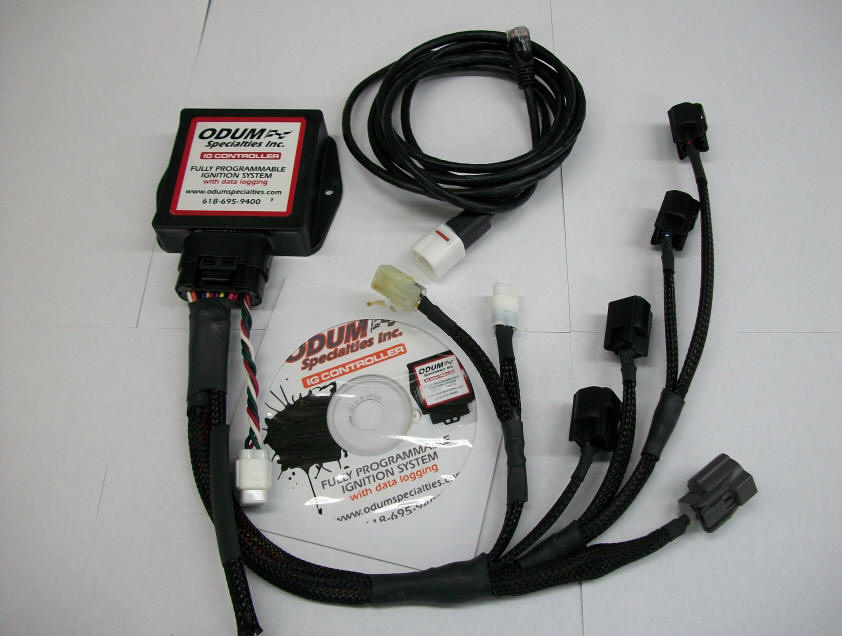
We no longer sell the controller, but we still make the harness IG Controller Ignition System with Data Logger Click on picture for a video of software
Plug and Play $750.00*
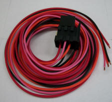
Our new IG Controller is a fully programmable Ignition system that can be programmed to work on most 1 to 4 cylinder motors. IG Controller Accessories IG Controller comes with controller, controller programmed for your motor, tuning software, tuning cable and basic wiring harness: consisting of coil ends, camshaft and crankshaft sensor connectors. *above picture is shown with optional TPS sensor connector installed.
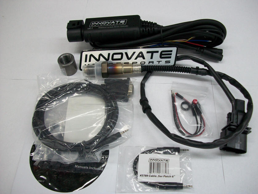
Innovate Wideband O2 System $210.99 Wideband, wired up to IG Controller and programmed $260.99
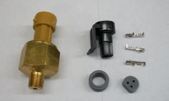
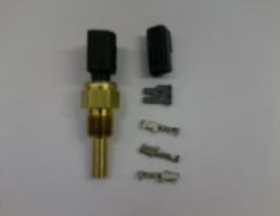
Fluid Pressure Sensor $69.54 Fluid Temperature Sensor $44.90 Sensor, wired and programmed $95.54 Sensor wired and programmed $69.90
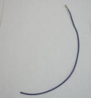
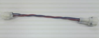
12 inch pigtail with IG Connector end $2.00ea Power Relay Kit $21.99 Relay Kit, wired and programmed for, Fuel pump, Cooling fan, Ignition, etc $41.99ea.
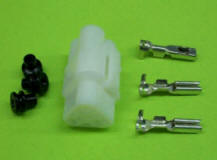
TPS Sensor connector end $8.00 Engler TPS Sensor Extension $20.00 TPS Sensor connector wired and programmed. $18.00
IG Controller tuning software Below are screen shots showing you just a few options you have.
This screen shot shows several options open at the same time.
IG Controller Data Acquisition Screen On this screen you can setup your data logger to your preferences.
Engine Setup Screen Used to setup the number of cylinders, types of camshaft and crank sensors.
These setting should not be changed. (Different type coils require different charge times.)
Ignition Compensations can be enabled here.
This screen sets up your crankshaft sensor. (Do not change unless you know what your doing.)
You can setup your rev limiter and how the rev limiter will operate.
Ignition timing table to adjust your timing curve.
The tuning slider is a perfect tool for working with a dynometer. You can quickly add or reduce timing across the whole timing curve.
This screen is where you setup the sensors you are using, such as coolant, O2 sensor, Fuel pressure, TPS, etc.
You can change the Timing table rpm and TPS table settings.
Setup your three analog input channels such as O2 sensor, fuel pressure, oil pressure, oil temperature, etc.
You can name your two digital inputs and one digital output here.
You can setup two different timing curves and switch between them if you prefer.
A light can be setup to flash when IG Controller sees a problem just like your family car does.
On / off controls are setup so you can operate your one digital output such as a cooling fan or fuel pump relay.
This option you can check to see if your camshaft and crankshaft sensors are properly wired. A great diagnostic tool!
System Status will let you know if the IG Controller sees a problem and how many times the problem occurs.
System information.
Here you can manually operate the coils and digital outputs.
Input Diagnostics will show the reading for your inputs.
IG CONTROLLER Pin Identification Table
|
|
|